WHITE PAPERS
from the files of
Networking Unlimited, Inc.
Performance Impact of Backbone Speed in Switched LAN Architectures
Dr. Vincent C. Jones, PE
WhitePapers@NetworkingUnlimited.com
Version 2.00 -- 31 May 2001
The use of a high speed backbone architecture in an extended LAN architecture can have significant impact on the performance seen by users of client/server applications (such as high performance file servers). The problem is the introduction of additional delay in the link between client and server if both are not on the same physical LAN segment. While normally not a problem for protocols which pipeline the data (using a window size greater than one), the added delay of just a single bridge can have a significant deleterious impact on the "ping-pong" mode of operation common in PC applications. This can be a critical challenge in a modern switched network because upgrading to a higher backbone speed can actually decrease end-to-end performance. The cause of the performance deterioration is explored, the actual impact calculated for various scenarios, and techniques which can be used to minimize the impact discussed.
Background
Many PC-centric LAN protocols were designed to avoid the inability of early PC Ethernet interface hardware to handle back-to-back packets. The 9.6 µsec interframe gap defined in the Ethernet and 802.3 standards was not enough time for low cost PC interfaces to transfer a frame of data to the PC and be ready to receive the next frame. As a result, the arrival of back-to-back frames would result in the interface dropping one frame or the other, dramatically slowing down the transfer of data as timeouts would have to expire before the loss was detected.
To avoid problems with back-to-back packet arrivals, many PC
protocols (including Netware and typical NetBEUI implementations)
were implemented with a window size of one. That is, a packet could
not be transmitted until the previous packet was acknowledged. This
way, there was no danger of a high performance server sending data to
a client PC faster than the client PC could handle it. At the same
time, the few extra microseconds required to receive a response after
each data packet had only a minor impact on performance (at 10Mbps,
sending a 60 byte request/acknowledgement adds only 58 µsec to
the 1220 µsec required to send each maximum sized
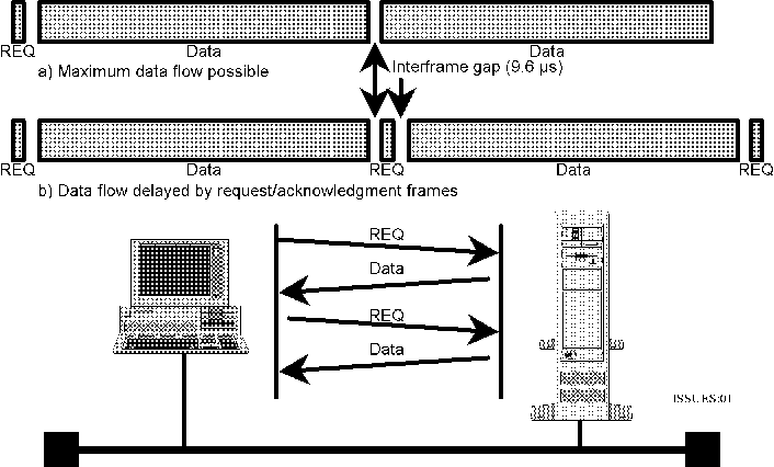
Ethernet/802.3 frame). This is shown graphically in figure 1.

Figure 1: Ideal LAN performance using "ping-pong" protocol.
While the performance impact of introducing delay is most severe in classical PC applications, it will have an impact on any application which is designed to stop and wait for a response after transmitting. It can also affect otherwise immune protocols. For example, it will slow down the ramp up of window size on a TCP connection because of the TCP "slow-start" congestion control mechanism.
Impact of Bridging
Adding a local bridge between the client and the server more than
doubles the delays due to the network. This is due to two factors.
First, the bridge must wait until the entire frame is received before
forwarding takes place to avoid forwarding defective packets. Second,
typical bridges require time to process each frame. For example, a
5000 frame per second maximum forwarding rate bridge has 1/5000 of a
second, or 200µs, to process each frame, so the total time
required to deliver a maximum sized Ethernet frame is the sum of the
time required to receive the frame plus the time required to process
it plus the time required to transmit the frame on the destination
network = 1211 + 200 + 1211+ 9.6 = 2632 µs rather than the 1220
µs required for a same segment transfer. This has significant
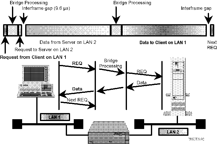
impact on effective transaction delay as illustrated in figure 2.

Figure 2: Impact of inserting a bridge on "ping-pong" protocol performance.
The additional network delay is not a major problem with protocols that allow pipelining, such as TCP/IP and OSI. However, when pipelining is not provided, the additional delay can have a dramatic impact on network throughput as well, as only one packet of data can be delivered for each round trip. The actual impact will depend upon the speed of the client and the server, but will be greater the faster the system. Table 1 summarizes the performance hit for various combinations of measured speed over a single segment and three different bridge performance levels (typical, maximum required to keep up with a worst case Ethernet LAN, and perfect bridge with no processing delay).
|
Bridge Between LANs |
Throughput (Kbytes/sec) |
||
|---|---|---|---|
|
Application baseline (no bridge) |
1000 |
500 |
200 |
|
Perfect Bridge (no delay) |
543 |
352 |
171 |
|
15,000 packets/second |
518 |
341 |
169 |
|
5,000 packets/second |
474 |
322 |
164 |
Table 1: Throughput impact of a local bridge between two 10Mbps LAN segments
The application baseline is the intrinsic speed of the client/server combination, as measured on a dedicated 10Mbps LAN segment. Note that the bridge speed is not that important a factor, as the biggest delay is the time required to transmit the data packet a second time. The chart assumes maximum efficiency using full maximum size 802.3 frames and 802.2 LLC for carrying data from server to client (1496 actual data bytes in each frame), as is commonly seen using LAN Manager over NetBEUI. Novell Netware by default uses smaller data packets and has more overhead (IPX and SPX protocol headers) per frame, so the impact is even greater.
Impact of Switching
To get the traffic isolation benefits of bridging without the concomitant performance hit requires the use of cut-through switches. Cut-through switches do not wait for the entire frame to be received before starting to transmit out the other side. Delay is not entirely eliminated because the switch still has to wait for enough of the frame to arrive to read the destination address before it can even start processing. Ethernet switches will normally wait long enough to avoid forwarding frames aborted by normal collisions, about 50 µs for 10 Mbps Ethernet and 5 µs for 100 Mbps. Using a 50 µs Ethernet switch in place of a store-and-forward bridge slows a 1000 Kbytes/s application down to 937 Kbytes/s, while a 200 Kbytes/s application drops by only 3 Kbytes/sec.
Another way to think of it is to look at the maximum theoretical
data rate sustainable with perfect clients and servers (where the
delay before responding or requesting the next packet is determined
by the Ethernet/802.3 interframe gap specification of 9.6 µs.
Under these conditions, a dedicated LAN segment can deliver 1180
KBytes/s, which drops to 1101 KBytes/s when the delay of an Ethernet
switch is introduced. A transparent bridge, on the other hand, even
one with no processing delay, can only deliver 594 KBytes/s at best.

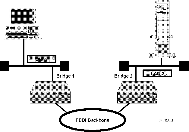
Figure 3: Bridged network architecture using a high-speed backbone network.
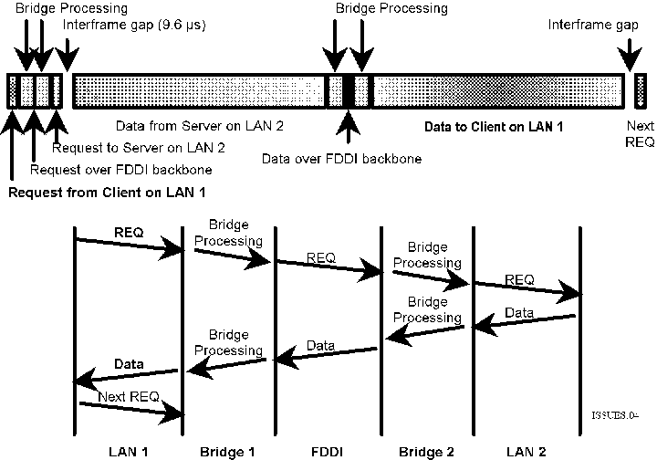
Moving to a high speed backbone network, such as that in figure 3,
can actually slow down the network, as can be seen from the timing
diagram in figure 4. Unlike the local bridge environment, the high
speed of the backbone prevents taking advantage of a cut-through
switching approach. Since transmission of the frame on the 100 Mbps
network can only start after at least 90% of the incoming 10 Mbps
frame has been received in order to not run out of data while
sending, commercial switches do not even attempt to cut through when
switching between unequal speeds. The impact on performance of
various combinations of access network and backbone network speeds is
summarized in Table 2.

Figure 4: Timing relationships for a high-speed backbone bridged or routed architecture.
|
Network Configuration |
Application Throughput |
||||
|---|---|---|---|---|---|
|
Client LAN |
Backbone |
Server LAN |
Kbytes/sec |
Kbytes/sec |
Kbytes/sec |
|
Application Baseline (single LAN) |
1000 |
500 |
200 |
||
|
10 Mbps |
10 Mbps |
10 Mbps |
882 |
469 |
195 |
|
10 Mbps |
100 Mbps |
10 Mbps |
519 |
342 |
169 |
|
10 Mbps |
1 Gbps |
10 Mbps |
539 |
350 |
171 |
|
10 Mbps |
10 Gbps |
10 Mbps |
541 |
350 |
171 |
Table 2: Throughput impact of mismatched access LAN speed and backbone speed. 10 to 10 cut-through with 50 µs delay and store & forward with no processing delays between differing speeds.
Note that even upgrading the backbone to 10 Gbps provides little relief, reducing by only 2% the 41% performance drop from a 10 Mbps to 100 Mbps backbone upgrade. The fundamental problem is that any time the speed of the incoming frame and the outgoing frame are not identical, the entire frame must be received from one network before being forwarding onto the other. From a practical viewpoint, there are three ways to address the challenge. The network segments can be connected in a way that does not introduce significant delay (Delay Elimination), a protocol whose throughput is less sensitive to delay can be used (Pipelined Protocols), or enough bandwidth can be thrown at the network to make the degradation immaterial (Bandwidth Overkill). We will look at each in turn.
Delay Elimination
In the old days of 10 Mbps Ethernet, the best approach was to eliminate the cause of the problem. While more difficult to achieve using today's higher speed networking technologies, the goal remains a valid one. By using a physical network topology which eliminates the need to use bridges between servers and their primary clients, we can avoid introducing any significant delays between client and server.
The lowest cost solution is to simply keep all the clients and their associated servers on the same LAN segment. With today's twisted-pair technology, this means designing the network so all the members of the cluster run at the same data rate and attach to the same hub. This usually means locating the server close to the users, such as in the wiring closet or at a user location. On the down side is the need to keep all clients close to the server, which means that servers used by more than a single cluster of users will typically not be able to take advantage of this approach. It also prevents locating servers in the computer room or other centralized location for ease of maintenance and operations.
A popular approach for 10 Mbps networks that permits moving the servers into the computer room or expanding the client community to multiple clusters is to use remote repeaters to connect the server LAN segment and the client LAN segments into a single extended segment. Repeaters introduce a delay of only 0.1 µs (100 nanoseconds), so their impact on performance is imperceptible. On the other hand, repeaters also provide no traffic isolation, as their only function is to extend the physical limits of the Ethernet.
Unfortunately, remote repeaters are not an option with the higher speed Ethernet technologies (100baseT Fast Ethernet and 1000baseT Gigabit Ethernet) popular today. Even at 10 Mbps, care must be taken to stay within the standard limits for repeated segments (no more than four half-repeaters and 1000m of inter-repeater cable between any two systems). In large building wiring systems with backbone networks, the repeater links are run in parallel to the backbone, effectively extending the dimensions of individual LAN segments that then communicate peer-to-peer over the backbone.
Another limitation of this approach is that it assumes that each server has a well defined, unique community of clients associated with it. As organizations move to shared "super-servers" and cross-organization information sharing, this assumption tends to break down. It is also inconsistent with redundant switching designs which may be preferred in order to eliminate single points of failure in the network design.
Pipelined protocols
The "correct" way to solve the problem is to eliminate the sensitivity to delay at the protocol level. This means using a protocol which supports pipelining of transmissions, continuing to send additional data while waiting for an acknowledgment to what has already been sent. All protocols designed for wide area network use where significant delays are common, such as the DECnet, TCP/IP and OSI protocol stacks, use data pipelining to keep data flowing even though responses are delayed. This is often called windowed flow control, the name of the most common technique used to manage data flow when pipelining. Even most of the problem protocols, such as NetBEUI and Novell NCP, use windowed flow control. The problem is, they default to using a window size of one (ping-pong mode).
Changing the protocol stack, while it can eliminate the sensitivity to delay, has disadvantages. Most important, it replaces something that works with something that is untested and unfamiliar. The more sophisticated protocols also tend to require more configuration and more client resources, which can be a challenge in low end applications. However, due to Moore's Law and growing sophistication in PC operating environments, resource constraints are rarely the issue they used to be in the days of DOS and Windows for Workgroups.
It is also possible in many cases to simply "open up the window" for the current protocol. This is done in the Novell IPX world by enabling "Burst Mode." For NetBEUI, it requires changing the logical link control configuration to a larger window size. There are several problems associated with this approach, however. Most critical is the inability of many older PC Ethernet cards to accept back-to-back packets. This is the reason the window sizes defaulted to one in the first place. Even if the interface is fast enough to handle the load, the software on the client system may not be (server hardware or software is rarely a problem in this respect). This can lead to slow performance, unreliable operation, random system crashes, or other undesirable side effects when the window size is made greater than one. On the other hand, if the client hardware is incapable of handling larger window sizes with PC oriented software, it will probably have trouble with more sophisticated protocol suites as well. From a planning and testing viewpoint, expanding the window size should be treated the same as a protocol replacement.
There are many who believe that this challenge does not apply to their environment. They are running the latest Windows and Novell servers and only run TCP/IP, the baseline standard for pipelined performance. What they are overlooking is that response delays still impact their application performance, just at a different level. While delay will not noticeably slow down the FTP transfer of a large file, it will impact the time required to establish a TCP connection between client and server. A complex web page requiring many TCP connections (one for each element) will load considerably slower, as will transaction-oriented applications which still must "ping-pong" for each transaction.
Consequently, while pipelining can solve some delay induced performance issues, it is not a cure-all either. At the same time, it must be recognized that while delays can be designed out of local area networks, they are inevitable in wide area networks where the speed of light becomes significant. Ultimately, the solution is an application design issue. If the application is designed to perform well despite delays, it will perform well regardless of the environment, allowing the network designer to concentrate on availability issues. Unfortunately, too many applications are designed and tested solely on high performance LANs, and the need to deal with real-world delays is not recognized until after the application is in production and no longer running on an isolated test network.
Bandwidth Overkill
Today, the most popular method of dealing with the store and forward delays introduced by mismatches in LAN speeds is to simply throw more bandwidth at the problem. Rather than limit the speed upgrade to the backbone, we upgrade the speed of the access LANs at each end as well. Table 3 examines the impact on performance of a number of popular speed combinations. We also look at the impact on a 10 Mbyte/sec application, a performance level unattainable on a 10 Mbit/sec LAN.
|
Network Configuration |
Application Throughput |
|||||
|---|---|---|---|---|---|---|
|
Client LAN |
Backbone |
Server LAN |
Kbytes/sec |
Kbytes/sec |
Kbytes/sec |
Kbytes/sec |
|
Application Baseline (single LAN) |
10000 |
1000 |
500 |
200 |
||
|
10 Mbps |
10 Mbps |
10 Mbps |
N/A |
882 |
469 |
195 |
|
10 Mbps |
100 Mbps |
100 Mbps |
N/A |
855 |
461 |
193 |
|
100 Mbps |
100 Mbps |
100 Mbps |
8820 |
986 |
497 |
199 |
|
100 Mbps |
1 Gbps |
100 Mbps |
5175 |
915 |
478 |
196 |
|
100 Mbps |
1 Gbps |
1 Gbps |
8683 |
985 |
496 |
199 |
|
100 Mbps |
10 Gbps |
1 Gbps |
9147 |
990 |
497 |
199 |
Table 3: Throughput impact of mismatched access LAN speed and backbone speed. 10 to 10 cut-through with 50 µs delay, 100 to 100 and faster cut-through with 5 µs delay, and store & forward with no processing delays between differing speeds.
As can be seen in Table 3, upgrading all links to 100 Mbps and using 5 µs cut-through swtiches degrades the baseline 1000 Kbyte/sec application by less than 2% compared to the 12% degradation when using 10 to 10 cut-through bridges. We also see that there is only a 3% difference in performance between 10-10-10 and 10-100-100. So the impact of upgrading the backbone to 100 Mbps can be almost eliminated by also upgrading the LAN at the server end. The same pattern emerges when we consider 100 Mbps access LANs connected by a 1 Gbps backbone. Again we need to upgrade both the backbone and the server access speed to avoid significant degradation.
WARNING NOTE: The delays assumed for cut-through at 1 Gbps and store-and-forward between 1 and 10 Gbps are almost certainly different from real switches and become significant when looking at 10 Gbps performance. At 10 Gbps, a cut-through delay of 5 µsec is four times the 1.2 µsec serialization delay of a 1520 byte frame. In real life, it is unrealistic to expect cut-through to take longer than store-and-forward.
Bottom Line
Cut-through switching provides most of the benefits of bridging but reduces the delay to a low constant by starting to forward the incoming packet before it has been completely received and verified error-free. When first installed, cut-through switches usually have negligible performance impact. However, introducing speed mismatches, such as by upgrading the backbone network between switches, can have a significant performance impact by forcing the switches to revert to store-and-forward mode.
The "by the book" solution to the performance impact of added delays is to fix the applications being used so they are not susceptible to delay-induced performance degradation. This is the only solution which works with large wide area networks where the speed of light introduces unavoidable propagation delays on the order of 3 ms per 1000 Km (5 ms per 1000 miles). However, we often do not have the option of fixing the application available, particularly with commercial software.
On local and metropolitan sized networks, performance impact can be minimized by upgrading all performance critical clients and servers to the same high speed as the backbone network. However, this can be expensive because of the large number of high performance ports and interfaces typically required to service all users.
An acceptable alternative in many application environments is to leave the client LANs at the current speed and limit the upgrade to the backbone and back end networks. As long as both the backbone and the server access LANs run at the same higher speed, the performance degradation compared to keeping all three speeds identical is minor.
The correct solution, of course, will depend upon the specific needs of the organization, existing hardware and software which must be supported, and strategic plans for future network architectures.
![]()
Home
Page | Company
Profile | Capabilities
| Coming
Events | Case
Studies
| White Papers
| Book
Copyright 2001 © Networking Unlimited Inc.
All rights reserved.