WHITE PAPERS
from the files of
Networking Unlimited, Inc.
Redundant Routes in IPSec VPNs
Dr. Vincent C. Jones, PE
WhitePapers@NetworkingUnlimited.com
Version 1.00 -- 11 December 2002
Building a virtual private network (VPN) using IP Security Protocol (IPSec) is a popular cost-saving approach to wide area networking. One disadvantage of using a VPN is the scarcity of convenient tools to provide resilience in the face of router, firewall, or network failure. The challenge is to automatically detect failure of an IPSec connection so that an alternate route can be used. This white paper looks at two different approaches Networking Unlimited, inc. has used to meet the challenge: using a GRE tunnel to make the IPSec transport appear as a point-to-point link so that conventional routing protocols such as OSPF or EIGRP can be used, and using a routing protocol which does not require "neighbors" to be adjacent such as BGP directly over the IPSec transport. Example Cisco router configurations, adapted from production networks designed by Networking Unlimited, Inc., are provided for each approach.
Background
Virtual Private Networks (VPNs) are growing in popularity due to their ability to reduce WAN costs. Tempering this growth trend is the difficulty of providing useful redundancy so that network operations can continue uninterrupted despite failures that disrupt the ability of a particular link to carry traffic.
The underlying challenge is that useful redundancy requires the ability to detect when a link is down so that an alternate link, such as dial backup or a VPN through another ISP, can be used. If a failed link is not detected, it becomes a black hole for all traffic attempting to use that link. Link failure detection is normally provided by link layer keepalives or a routing protocol at the network layer. The problem is that neither approach, as used with conventional network links, works with IPSec tunnels.
Interior gateway protocols such as RIP, OSPF, and Cisco's EIGRP assume that routing exchanges are always between routers on a common subnetwork. While there is considerable flexibility in the choice of underlying subnetworks, ranging from Ethernet LANs to ATM and frame relay WANs, there is no provision for supporting neighbor relationships between routers that are not on the same IP subnetwork. In a VPN where the connectivity is via IPSec tunnels, this adjacency requirement is no longer satisfied, and configurations suitable for point-to-point or LAN links won't work.
Adding to the confusion are the many different ways that a VPN can be implemented. While all approaches may provide similar functionality to the end user, they can be very different from the point of view of the routers trying to establish and maintain reliable communications. Even a decision as rudimentary as whether separate routers and firewalls will be used or the functions will be combined within a single appliance, can fundamentally change the available solutions.
In this white paper we will look at two example VPN networks. While both required dynamic routing over IPSec transport, the underlying constraints and functional requirements were very different. In the first example, a conventional private WAN based on a partial mesh of point-to-point links was modified to use IPSec over the Internet. One key constraint was that no additional hardware, such as firewalls, could be used. All routing, firewall, and IPSec functions had to be provided by the one router at each site. Sites requiring high availability had two Internet links, one provided by a conventional point-to-point link to an ISP, the other provided by a wireless link (accessed via Ethernet) to another ISP.
In the second example, ISDN backup was added to a remote office using an IPSec tunnel to access corporate headquarters. In this scenario, the IPSec VPN was implemented using firewalls connected to same LAN as the users and simultaneous Internet access (via the firewall) was also required. Since the router was only used for ISDN backup, cost was again a major consideration. Also required was keeping the path MTU at the full 1500 bytes possible on an Ethernet. This meant that a conventional GRE-based solution could not be used. Instead, BGP was used to determine link status directly over the IPSec transport, and production traffic was routed via dial-on-demand ISDN any time the VPN was down.
IPSec Configuration
Consider two LANs connected by an IPSec tunnel configured between two firewalls, one at each LAN location, as in Figure 1. The details of the firewall configuration and any external routers required for Internet connectivity are irrelevant. The critical assumption is that the firewall will encapsulate and forward any traffic explicitly addressed to end-systems at the far end of the tunnel, provided that it's received on a specific local IP address assigned to the firewall. The challenge is that, to the routers on the inside networks, the firewalls behave like routers but don't participate in any dynamic routing protocol exchanges. That is, the firewalls only support forwarding of unicast packets along unchanging routes to predefined destinations.
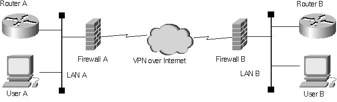
Figure 1: A typical VPN configuration.
In this typical application scenario, the routing limitations inherent in an IPSec tunnel are not an issue. If the VPN is up, the two sites can communicate and if the VPN is down, they cannot. But consider what happens when we attempt to improve availability by adding a second path between the two sites, as in Figure 2.
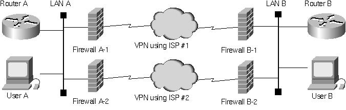
Figure 2: A redundant VPN configuration.
Because the links between the firewalls and the routers are Ethernet, there is no way for the router to detect firewall or IPSec failure at the link level. At the same time, traditional interior gateway protocols only function between adjacent routers, so there's no convenient way to set up a router-to-router association across the channel provided by the firewalls.
The standard approach for providing routing support in this situation is to define a generic routing encapsulation (GRE) tunnel between the routers that uses the IPSec tunnel for its transport. This provides a logical point-to-point link between the two routers capable of supporting any desired routing protocol. However, this approach has two significant disadvantages:
1. It forces the routers to handle every packet, encapsulating each packet before sending it over the tunnel and then extracting each packet at the other end. This not only introduces delay but also increases the processor loading on the router.
2. Using a GRE tunnel reduces the maximum transfer unit (MTU) for the path by the overhead of GRE encapsulation. So if the IPSec tunnel MTU is 1500 bytes (the maximum allowed by the Ethernet link to the firewall), the GRE tunnel used for all production traffic will be only 1476 bytes. Newer Cisco IOS releases allow defining a higher MTU on a GRE tunnel than can be physically supported, but this is often not desirable because although it allows systems with borken path MTU discovery to communicate, it also encourages systems with working path MTU discovery to unnecessarily suffer from packet fragmentation and reassembly.
As it turns out, there are two approaches we can take to eliminate the impact of GRE overhead on the available MTU size. If the ISP supports packet sizes larger than 1500 bytes, we can remove the firewalls, put the router where the firewalls were, and perform all functions in one box. This reduces the amount of hardware required, potentially saving money. However, the savings must be balanced against the increased complexity of the router configuration, which can increase life cycle costs. We will explore this approach in the next section.
Alternatively, we can keep the hardware as it is, and use a routing protocol which can work through the firewalls and IPSec transport without the complexity of the path being hidden by a GRE tunnel. The Border Gateway Protocol (BGP) works very well for this purpose, and we will explore that approach after looking at the conventional GRE approach.
VPN Routing Using Generic Routing Encapsulation
The traditional approach to allow routing with IPSec tunnels is to use Generic Routing Encapsulation (GRE) to make the IPSec tunnel look like a conventional point-to-point link. We have already discussed the disadvantages of this approach, but just because it has disadvantages does not mean that it is not a useful approach, particularly if we can eliminate the need to reduce the path MTU to make up for the GRE overhead.
In the example which follows, we do not compensate for path MTU reduction because the backup path, a wireless ISP, only provided an Ethernet interface to their equipment. Fortunately, the applications in use correctly implemented path MTU discovery, so the MTU reduction was not an issue. What was an issue was minimizing "parts count," so a single router per site with no firewall was desired. (Note that this approach may not result in a lower price for the installed solution, because the cost of adding firewall features to the router in order to support IPSec sometimes exceeds the cost of a standalone firewall).
Figure 3 shows the solution implemented. Although we could have increased the MTU on the serial links, allowing 1500 byte payloads to be carried despite the overhead of GRE and IPSec, this approach was rejected because that would require the applications to discover and adjust the path MTU whenever traffic was required to use the backup path via wireless. The wireless path, because it was Ethernet connected, had to fit GRE IPSec packets into the 1500 byte Ethernet limit. While we could have used the Cisco IOS feature to force GRE to pretend the MTU is higher than it actually is, the impact on performance was deemed unacceptable.
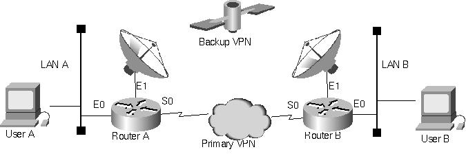
Figure 3: Example of redundant VPN routing with OSPF
! Site A with redundant VPN connectivity to Site B
!
! WARNING: Appropriate protection for a router directly
! connected to the Internet is not included.
! See access-list 199 for IPSec minimum permissions.
!
version 12.1
!
hostname Router_A
!
crypto isakmp policy 1000
authentication pre-share
lifetime 84600
crypto isakmp key secret111 address 1.1.1.1
crypto isakmp key secret222 address 2.2.2.1
!
crypto ipsec transform-set IMparanoid ah-sha-hmac esp-des esp-sha-hmac
mode transport
!
crypto map pathOne local-address Serial0
crypto map pathOne 1 ipsec-isakmp
set peer 1.1.1.1
set transform-set IMparanoid
match address 101
!
crypto map pathTwo local-address Ethernet0
crypto map pathTwo 2 ipsec-isakmp
set peer 2.2.2.1
set transform-set IMparanoid
match address 102
!
interface Tunnel1
bandwidth 1544
ip address 172.16.255.1 255.255.255.252
ip nat inside
tunnel source 3.3.3.1
tunnel destination 1.1.1.1
crypto map pathOne
!
interface Tunnel2
bandwidth 512
ip address 172.16.255.101 255.255.255.252
ip nat inside
tunnel source 4.4.4.1
tunnel destination 2.2.2.1
crypto map pathTwo
!
interface Ethernet0
description Local LAN
ip address 172.20.100.1 255.255.252.0
ip nat inside
!
interface Ethernet1
description Wireless Link to ISP 2
ip address 4.4.4.1 255.255.255.224
ip access-group 199 in
ip nat outside
crypto map pathTwo
!
interface Serial0
description T1 Link to ISP 1
ip address 3.3.3.1 255.255.255.252
ip nat outside
crypto map pathOne
!
router ospf 1
passive-interface Ethernet1
passive-interface Serial0
network 172.20.100.1 0.0.3.255 area 5
network 172.16.255.0 0.0.0.3 area 5
network 172.16.255.100 0.0.0.3 area 5
!
ip nat inside source route-map link1 interface serial 0 overload
ip nat inside source route-map link2 interface ethernet 0 overload
!
ip classless
ip route 0.0.0.0 0.0.0.0 4.4.4.2 100
ip route 0.0.0.0 0.0.0.0 3.3.3.2 100
ip route 1.1.1.1 255.255.255.255 3.3.3.2 100
ip route 2.2.2.1 255.255.255.255 4.4.4.2 100
!
access-list 101 permit gre host 3.3.3.1 host 1.1.1.1
access-list 102 permit gre host 4.4.4.1 host 2.2.2.1
! Access list openings required to support IPSec to Site-1 via wireless
access-list 199 permit gre host 1.1.1.1 host 4.4.4.1
access-list 199 permit esp host 1.1.1.1 host 4.4.4.1
access-list 199 permit udp host 1.1.1.1 host 4.4.4.1 eq isakmp
! Since we're testing, let in everything else as well
access-list 199 permit ip any any
!
route-map link1 deny 15
match ip address 101
route-map link1 permit 25
match interface Serial0
!
route-map link2 deny 15
match ip address 102
route-map link2 permit 25
match interface Ethernet0
!
end
Listing 1: Router A using OSPF routing inside redundant GRE tunnels over IPSec VPNs.
! Site B on "the other side of the Internet"
!
! WARNING: Appropriate protection for a router directly
! connected to the Internet is not included.
!
version 12.1
!
hostname Router_B
!
crypto isakmp policy 1000
authentication pre-share
lifetime 84600
crypto isakmp key secret111 address 3.3.3.2
crypto isakmp key secret222 address 4.4.4.1
!
crypto ipsec transform-set IMequallyParanoid ah-sha-hmac esp-des esp-sha-hmac
mode transport
!
crypto map pathOne local-address Serial0
crypto map pathOne 1 ipsec-isakmp
set peer 3.3.3.1
set transform-set IMequallyParanoid
match address 101
!
crypto map pathTwo local-address Ethernet0
crypto map pathTwo 2 ipsec-isakmp
set peer 4.4.4.1
set transform-set IMequallyParanoid
match address 102
!
interface Tunnel10
bandwidth 512
ip address 172.16.255.2 255.255.255.252
ip nat inside
tunnel source 1.1.1.1
tunnel destination 3.3.3.1
crypto map pathOne
!
interface Tunnel20
bandwidth 512
ip address 172.16.255.102 255.255.255.252
ip nat inside
tunnel source 2.2.2.1
tunnel destination 4.4.4.1
crypto map pathTwo
!
interface Ethernet0
description Example LAN for local users
ip address 172.22.22.22 255.255.255.0
ip nat inside
!
interface Ethernet1
description Wireless or other link to ISP
ip address 2.2.2.1 255.255.255.240
ip nat outside
crypto map pathTwo
!
interface Serial0
ip address 1.1.1.1 255.255.255.252
ip nat outside
crypto map pathOne
!
router ospf 1
passive-interface Ethernet0
passive-interface Serial0
network 172.22.22.0 0.0.0.255 area 5
network 172.16.255.0 0.0.0.3 area 5
network 172.16.255.100 0.0.0.3 area 5
!
ip nat inside source route-map linkSerial interface Serial0 overload
ip nat inside source route-map linkEthernet interface Ethernet0 overload
ip classless
ip route 0.0.0.0 0.0.0.0 1.1.1.2 100 ! via Serial
ip route 0.0.0.0 0.0.0.0 2.2.2.2 100 ! via Wireless
ip route 3.3.3.1 255.255.255.255 1.1.1.2
ip route 4.4.4.1 255.255.255.255 2.2.2.2
!
access-list 101 permit gre host 1.1.1.1 host 3.3.3.1
access-list 102 permit gre host 2.2.2.1 host 4.4.4.1
!
route-map linkSerial deny 15
match ip address 101
route-map linkSerial permit 25
match interface Serial0
!
route-map linkEthernet deny 15
match ip address 102
route-map linkEthernet permit 25
match interface Ethernet0
!
end
Listing 2: Router B using OSPF routing inside redundant GRE tunnels over IPSec VPNs.
VPN Routing Using Border Gateway Protocol (BGP)
Rather than use a GRE tunnel, we can take advantage of the ability of the Border Gateway Protocol (BGP) to establish routing neighbor relations between non-adjacent routers. Exterior gateway protocols such as BGP are designed to function in an environment where not all routers support the routing protocol.
Using BGP between the routers, we can establish a neighbor relationship and exchange routes as if the two routers were adjacent. This is a little bit tricky because we need to configure the route between routers using explicit static routes (BGP will not use a default route). At the same time, we do not want that static route to be used for production traffic; otherwise, it creates a black hole when the VPN goes down. Rather than a static route pointing all traffic to the distant LAN to the IP address of the local firewall VPN interface, we define a static host route for only the IP address of the LAN interface on the remote router.
Once we have BGP routing exchanges working between the two routers, we can use standard dial-on-demand routing (DDR) to implement dial backup. That way, as long as the IPSec tunnel is up, BGP will learn the networks accessible via the VPN, and traffic for systems on the remote LAN will be routed over the VPN. Any time there's a problem with the IPSec tunnel, whether due to firewall, link, or ISP problems, BGP will time out from the lack of hello exchanges, remove the routes from the routing table, and the DDR floating static route(s) will take over and the next packet destined to the remote side will force up the ISDN link, restoring production communications.
In the example in Figure 4, we have a single IPSec link between firewalls at each site and implement conventional ISDN dial backup to provide continuity of operations despite VPN failures.
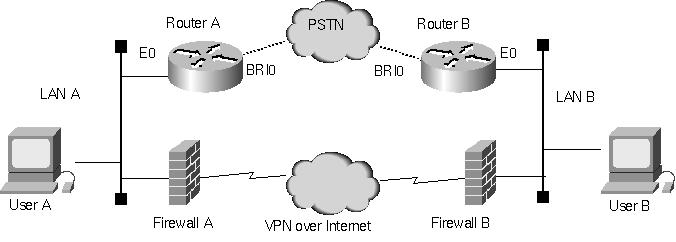
Figure 4: BGP-driven dial backup for a VPN link.
! Dial Backup for VPN Configuration - Calling Side
!
version 12.0
!
hostname NewYork
!
username Denver password 0 mumble
!
isdn switch-type basic-ni
!
interface Ethernet0
ip address 192.168.98.1 255.255.255.0
no ip redirects
ip route-cache same-interface
!
interface BRI0
description backup to Denver
no ip address
encapsulation ppp
no keepalive
dialer rotary-group 0
dialer-group 1
isdn switch-type basic-ni
isdn spid1 21255598761111
isdn spid2 21255598771111
!
interface Dialer0
ip address 10.100.22.2 255.255.255.0
encapsulation ppp
no ip route-cache
dialer in-band
dialer map ip 10.100.22.1 name Denver broadcast 3035551234
dialer map ip 10.100.22.1 name Denver broadcast 3035551235
dialer-group 1
ppp authentication chap
!
router bgp 65500
no synchronization
network 192.168.97.0 mask 255.255.255.0
network 192.168.98.0 mask 255.255.255.0
! Add any other networks which need to be reached from Denver here
! or redistribute from the routing protocol used to learn them.
timers bgp 5 16
neighbor 192.168.99.1 remote-as 65500
neighbor 192.168.99.1 update-source Ethernet0
neighbor 192.168.99.1 route-map UseVPN2Denver in
!
ip classless
ip route 0.0.0.0 0.0.0.0 192.168.97.3
ip route 10.100.22.1 255.255.255.255 Dialer0
ip route 192.168.97.0 255.255.255.0 192.168.98.2
ip route 192.168.99.0 255.255.255.0 10.100.22.1 210
ip route 192.168.99.1 255.255.255.255 192.168.98.3 3
!
dialer-list 1 protocol ip permit
route-map UseVPN2Denver permit 10
set ip next-hop 192.168.98.3
!
end
Listing 3: Dial backup for a VPN network-Router placing the backup call.
! Dial Backup for VPN Configuration - Called Side
!
version 12.0
!
hostname Denver
!
username NewYork password 0 mumble
!
isdn switch-type basic-ni
!
interface Ethernet0
ip address 192.168.99.1 255.255.255.0
no ip redirects
ip route-cache same-interface
!
interface BRI0
description backup to NewYork
no ip address
encapsulation ppp
bandwidth 56
dialer rotary-group 0
dialer-group 1
isdn spid1 30355512340101
isdn spid2 30355512350101
!
interface Dialer0
ip address 10.100.22.1 255.255.255.0
no ip directed-broadcast
encapsulation ppp
no ip route-cache
dialer in-band
dialer map ip 10.100.22.2 name NewYork speed 56 broadcast
dialer-group 1
ppp authentication chap
!
router bgp 65500
no synchronization
network 192.168.99.0 mask 255.255.255.0
timers bgp 5 16
neighbor 192.168.98.1 remote-as 65500
neighbor 192.168.98.1 update-source Ethernet0
neighbor 192.168.98.1 route-map UseVPN2NewYork in
!
ip classless
ip route 0.0.0.0 0.0.0.0 192.168.99.3
ip route 10.100.22.2 255.255.255.255 Dialer0
ip route 192.168.97.0 255.255.255.0 10.100.22.2 210
ip route 192.168.98.0 255.255.255.0 10.100.22.2 210
ip route 192.168.98.1 255.255.255.255 192.168.99.3 3
!
dialer-list 1 protocol ip permit
!
route-map UseVPN2NewYork permit 10
set ip next-hop 192.168.99.3
!
end
Listing 4: Dial backup for a VPN network-Router receiving the backup call.
Although the configurations in Listings 3 and 4 are superficially standard dial-on-demand routing, a number of "tricks" are required to get everything to work correctly, particularly if BGP is also in use for other purposes. For example, if both routers are configured to be in the same autonomous system, which I recommend to keep the design simple, synchronization must be disabled or the routes learned by BGP will never be inserted into the local routing table. Modification of the BGP hello and dead timers is also desirable to minimize response time to VPN failure. However, that adjustment must be balanced against the extra packets that shorter timer values will require across the VPN. Users of low-end routers may also discover that BGP is not supported on the routers they currently have installed, so that hardware or software upgrades may be required.
Other mandatory configuration lines whose purpose may not be evident at first glance include disabling ICMP redirects with "no ip redirects" on the Ethernet interfaces. Otherwise, the router will try to instruct hosts using the VPN to go directly to the firewall, disabling their ability to access the ISDN link if the VPN fails. On Cisco routers, the "ip route-cache same-interface" allows fast switching of VPN traffic, which must pass through the router to get to the firewall even if the user and the firewall are already on the same LAN. A common oversight is forgetting to change the default gateway on the local hosts to go to the router instead of the firewall. Whether or not to support real Internet traffic when the VPN is down is another design consideration.
Bottom Line
VPN usage need not be restricted solely to applications with low or modest availability requirements. Network availability in a VPN environment can be significantly enhanced through support of redundant communications links, either in the form of VPNs through other ISPs or dial backup. The key is to use a routing protocol that can detect a VPN failure despite the operational limitations inherent in a VPN environment.
The configuration examples provided in this white paper are sanitized versions of redundant VPN configurations which have been in production use for over a year. While the BGP approach may be intimidating for those not familiar with the protocol, particularly if the only exposure is in big routers running defaultless on the Internet, it is worth investing the time and effort to really understand how the example given here works. In many environments, using BGP rather than a conventional interior gateway protocol running through GRE results in a simpler, more efficient configuration.
Please remember when designing a solution for your needs to keep security in mind. Any router which touches the Internet needs to be protected. While that protection is mandatory, it is not shown in the examples to keep the focus on VPN routing (the same as the configuration of other ports, SNMP management, enable secret, other routing protocols, etc. are assumed but not shown).
Please also remember that the examples provided in this white paper are just that, working examples of how redundant VPNs were configured for two specific applications. There are other ways that VPN reliability can be enhanced, just as there are other applications where VPNs are not a cost effective solution. You need to decide what is best for your requirements given your organization's abilities and the constraints of the specific application and environment.
![]()
Home
Page | Company
Profile | Capabilities
| Coming
Events | Case
Studies
| White Papers
| Book
Copyright 2002 © Networking Unlimited Inc.
All rights reserved.